
Zirconia restorations have become widely accepted in clinical dentistry due to their natural esthetics, excellent biocompatibility and exceptional flexural strength. However, zirconia is still a ceramic material with inherent brittleness. If the design, milling, or pre-sintering procedures are not properly controlled, fractures may occur either during fabrication or later in clinical use.
This article focuses on fracture risks that originate before the sintering stage, explaining the common causes and offering practical prevention techniques for dental labs.
Prosthetic design is one of the most decisive factors affecting the final strength of a zirconia restoration. Improper framework design can create stress concentration areas that lead to cracks or complete fractures.
Meet the minimum thickness requirements.
Pay special attention to the cervical margin. The minimum zirconia thickness in this area should not be less than 0.6 mm.
Ensure proper connector dimensions.
Anterior connectors: ≥ 9 mm²
Posterior connectors: ≥ 12 mm²
These dimensions help distribute occlusal forces more evenly across the bridge.
Limit continuous missing units.
A bridge should ideally span no more than two consecutive missing teeth.
Control pontic length.
The distance of the missing span should remain ≤ 20 mm to maintain stability.
Bridge span recommendations.
Zirconia bridges can be designed up to 14 units, but it is important to avoid cantilever designs whenever possible.
Implant-supported cases.
When designing implant bridges, keep screw-access holes away from thin margins and position them toward the center of occlusion for optimal strength distribution.
Improper nesting during CAM planning may cause fractures during milling or handling. Pay attention to the following points:
Minimize undercuts.
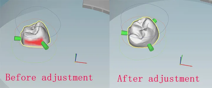
Adjust the nesting angle to reduce deep undercuts. This decreases the amount of post-milling grinding needed and lowers the risk of microcracks.
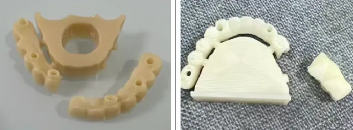
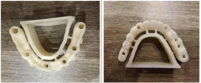
(Examples of full-arch sintering-frame fractures are commonly seen when the support structure is oversized.)
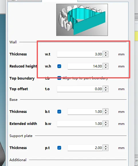
Proper sintering-frame thickness.
If the sintering support bar is too thick, it may shrink more than the restoration during sintering and pull the restoration apart.
Recommended thickness: 2.0–3.0 mm, similar to the diameter of the connector rods.
Correct placement of connector bars (sprues) is essential to maintain stability during milling and to prevent stress concentration before sintering.
Keep the connector bars as horizontal as possible.
This helps ensure that the restoration receives uniform force during sintering.
Avoid placing connector bars in areas with strong curvature, such as along the arch.
Excessive bending in these locations may increase stress and lead to tearing or deformation.
Position connector bars on prominent and easily accessible surfaces of the restoration.
This improves milling stability and reduces the risk of microcracks caused by vibration.
Use at least n + 2 connector bars (n = number of units).
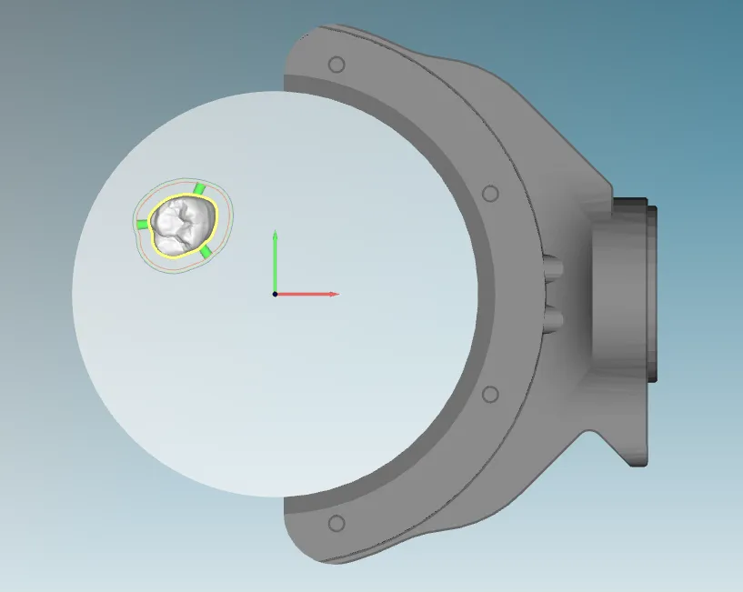
For example, a single crown should have a minimum of three connector bars, evenly spaced at roughly 120°, ensuring firm clamping and preventing movement during milling.
Equipment-related issues are a major cause of hidden cracks and fractures.
Before replacing a disc, clean the clamp holder thoroughly. Even a small amount of dust can prevent secure clamping and cause vibration.
Tighten all fixture screws evenly to avoid uneven force distribution, which may cause the zirconia blank to crack during milling.
Regular calibration is essential. Without calibration, milling marks or cutter lines appear, and deep tool paths may introduce microcracks.
Daily dust cleaning is strongly recommended. Excess dust in the spindle or guide rails affects precision and can contribute to fractures.
Dull burs cause chipping, edge fracture, or internal microcracks.
Replace burs on schedule, especially when milling high-strength zirconia.


